User:Thornfield Hall/Radio
From Wikipedia, the free encyclopedia
 MF
MF Comparison of the frequency bands defined by NATO, IEEE and ITU
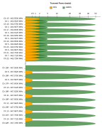 FRS and GMRS frequency spectrum usage, including bandwidth and maximum power allowances.
 A schematic showing the relationship between dBu (the voltage source) and dBm (the power dissipated as heat by the 600 Ω resistor)
 Animation showing a half-wave dipole antenna receiving power from a radio wave. The antenna consists of two metal rods each one-quarter of the wavelength long, attached through a parallel transmission line to a resistance R equal to the characteristic impedance of the antenna, representing the receiver. The electromagnetic wave is represented by its electric field (E, green arrows) (it should be kept in mind that the drawing only shows the field along one line, while the radio wave is actually a plane wave and the electric field is actually the same at every point on a plane perpendicular to the direction of motion). The wave's magnetic field is not shown. The oscillating electric field exerts force on the electrons in the antenna rods , causing them to move back and forth in currents (black arrows) between the ends of the antenna rods, charging the ends of the antenna alternately positive (+) and negative (−). Since the antenna is a half-wavelength long at the radio wave's frequency, it excites standing waves of voltage (V, red) and current in the antenna. The voltage along the antenna elements is represented graphically by a band of red whose thickness at any point is proportional to the magnitude of the voltage. The oscillating currents flowing back and forth from one antenna element to the other, pass down the transmission line and through the radio receiver, represented by R. In this animation the action is shown slowed down drastically; the radio waves received by dipoles actually oscillate back and forth at tens of thousands to billions of cycles per second.
 Animation showing standing waves on a half-wave dipole antenna driven by a sinusoidal voltage Vi from a radio transmitter at its resonant frequency. The oscillating voltage pushes the electrons back and forth along the two metal rods that make up the antenna, creating oscillating currents (blue arrows) in the antenna, charging its ends alternately positive (+) and negative (-). Since at this frequency the antenna is a half wavelength (λ/2) long, a sinusoidal wave of voltage or current takes exactly one cycle to make the round trip from one end of the antenna to the other and back, so the reflected waves reinforce each other. The antenna acts like an electronic resonater. Waves of current and voltage reflecting back and forth between the ends of the rods interfere to form standing waves, which radiate radio waves into space. The waves are shown graphically by bars of color (red for voltage V(x) and blue for current I(x)) whose width at each point is proportional to the amplitude of the wave at that point. The blue arrows show the direction of conventional current, flow of positive charge. The electrons oscillating back and forth in the antenne move in a direction opposite to the arrows. The action is shown slowed down enormously; the currents in an actual antenna oscillate back and forth 20 thousand to one billion times per second.
 Animation of a half-wave dipole antenna transmitting radio waves, showing the electric field lines. The dipole, in the center, consists of two vertical metal rods with an alternating current at its resonant frequency applied at its center from a radio transmitter (not shown) The voltage alternately charges the two ends of the antenna positive (+) and negative (−). Standing waves of current (red arrows) flow up and down the rods. The alternating voltage on the rods creates loops of electric field (black lines) that pinch off into closed loops and radiate away from the antenna at the speed of light. These are the radio waves. The radiated power is greatest in the horizontal direction, perpendicular to the antenna, and decreases to zero above and below the antenna, on the antenna axis. This picture only shows the electric field in a single plane through the antenna axis; the field is actually axially symmetrical about the antenna. The action is shown slowed down drastically in this animation; real radio waves oscillate at rates of thirty thousand to a billion cycles per second.
 Animation showing how a Yagi-Uda antenna works. It consists of 4 half-wave dipole antennas in a line; a driven element (E) which is connected to the transmitter and radiates the radio waves, and 3 parasitic elements, two directors (D1, D2) and one reflector (R) which act as resonators, absorbing and reradiating the waves from the driven element with a different phase. The radio waves from all 4 elements combine and interfere, increasing the power radiated in the desired direction (up) and decreasing the power radiated in other directions. The radio waves from each individual element (wavy moving lines) are shown in a different color. The waves in the forward direction are in phase, and interfere constructively, adding together to produce a higher signal strength, while the waves in the reverse direction are out of phase, partially canceling each other to produce lower signal strength in that direction.
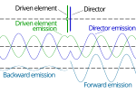 Schematics of a simple Yagi-Uda antenna with just a driven dipole and a director and their emitted fields
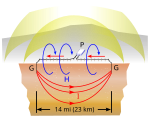 Diagram of ground dipole antenna used to transmit extremely low frequency (ELF) radio waves, showing how it works. This is modeled on the U.S. Navy ELF radio transmitter at Clam Lake, Wisconsin, which was used to communicate with submerged submarines at a frequency of 76 Hz from 1989 to 2004. The antenna consists of two electrodes buried in the Earth (G), 14 miles (23.5 km) apart, linked by overhead transmission lines resembling ordinary power distribution lines to a power plant transmitter (P). The system functions as a giant vertical loop antenna in which the earth serves as part of the loop. The power plant drives the antenna with 300 amperes alternating current at 76 Hz which flows through one transmission line, in looping currents (I) deep in bedrock from one ground electrode to the other, and back through the other transmission line (the drawing shows only one direction of the alternating current). The AC current creates an alternating magnetic field (H) which radiates ELF waves (yellow). The radiation pattern is directional, with two lobes (maxima) off the ends of the wire.
 Typical spectrum of extremely low frequency (ELF) electromagnetic oscillations in the Earth's atmosphere, showing peaks caused by the Schumann resonances. The Schuman resonances are the resonant frequencies of the spherical cavity bounded by the Earth and the ionosphere; lighning strikes and other sferics cause the Earth-ionosphere cavity to "ring" like a bell at these frequencies, causing peaks in the noise spectrum. The sharp power peak at 50 Hz is caused by radiation from global electric power grids. The rise of the noise at low frequencies (left side) is radio noise caused by slow processes in the Earth's magnetosphere.


More information Band name, Abbreviation ...
| Band name | Abbreviation | ITU band number | Frequency and wavelength | Example uses |
|---|---|---|---|---|
| Extremely low frequency | ELF | 1 | 3–30 Hz 100,000–10,000 km | Communication with submarines |
| Super low frequency | SLF | 2 | 30–300 Hz 10,000–1,000 km | Communication with submarines |
| Ultra low frequency | ULF | 3 | 300–3,000 Hz 1,000–100 km | Communication with submarines, communication within mines, landline telephony, fax machines, fiber-optic communication |
| Very low frequency | VLF | 4 | 3–30 kHz 100–10 km | Navigation, time signals, communication with submarines, landline telephony, wireless heart rate monitors, geophysics |
| Low frequency | LF | 5 | 30–300 kHz 10–1 km | Navigation, time signals, AM longwave broadcasting (Europe and parts of Asia), RFID, amateur radio. |
| Medium frequency | MF | 6 | 300–3,000 kHz 1,000–100 m | AM (medium-wave) broadcasts, amateur radio, avalanche beacons, magnetic resonance imaging, positron emission tomography, electrical telegraph, wireless telegraphy, radioteletype, dial-up internet. |
| High frequency | HF | 7 | 3–30 MHz 100–10 m | Shortwave broadcasts, citizens band radio, amateur radio, over-the-horizon aviation communications, RFID, over-the-horizon radar, automatic link establishment (ALE) / near-vertical incidence skywave (NVIS) radio communications, marine and mobile radio telephony, CT scan, magnetic resonance imaging, positron emission tomography, ultrasound, cordless phones. |
| Very high frequency | VHF | 8 | 30–300 MHz 10–1 m | FM broadcasts, television broadcasts, cable television broadcasting, radars, line-of-sight ground-to-aircraft, aircraft-to-aircraft communications, emergency locator beacon homing signal, radioteletype, land mobile and maritime mobile communications, amateur radio, police, fire and emergency medical services scanners, weather radio, CT scan, magnetic resonance imaging, positron emission tomography, ultrasound, cordless phones. |
| Ultra high frequency | UHF | 9 | 300–3,000 MHz 100–10 cm | Television broadcasts, cable television broadcasting, microwave oven, radars, microwave devices/communications, radio astronomy, radars (L band), mobile phones, wireless LAN, Bluetooth, Zigbee, GPS and two-way radios such as land mobile, emergency locator beacon, FRS and GMRS radios, amateur radio, satellite radio, police, fire and emergency medical services scanners, remote control systems, ADSB, cordless phones, internet, dial-up internet, satellite broadcasting, communication satellites, weather satellites, satellite phones (L band), satellite phones (S band). |
| Super high frequency | SHF | 10 | 3–30 GHz 10–1 cm | Radio astronomy, microwave devices/communications, wireless LAN, DSRC, most modern radars, communications satellites, cable and satellite television broadcasting, DBS, amateur radio, satellite broadcasting, communication satellites, weather satellites, satellite radio, cordless phones, internet, satellite phones (S band). |
| Extremely high frequency | EHF | 11 | 30–300 GHz 10–1 mm | Radio astronomy, satellite broadcasting, communication satellites, weather satellites, high-frequency microwave radio relay, microwave remote sensing, directed-energy weapon, millimeter wave scanner, Wireless Lan 802.11ad, internet. |
| Terahertz or tremendously high frequency | THF | 12 | 300–3,000 GHz 1–0.1 mm | Experimental medical imaging to replace X-rays, ultrafast molecular dynamics, condensed-matter physics, terahertz time-domain spectroscopy, terahertz computing/communications, remote sensing |
Close