Top Qs
Timeline
Chat
Perspective
Unified Modeling Language
Software design modeling notation From Wikipedia, the free encyclopedia
Remove ads
The Unified Modeling Language (UML) is a general-purpose, object-oriented, visual modeling language that provides a way to visualize the architecture and design of a system, like a blueprint.[1][2] UML defines notation for many types of diagrams which focus on aspects such as behavior, interaction, and structure.
UML is both a formal metamodel and a collection of graphical templates. The metamodel defines the elements in an object-oriented model such as classes and properties. It is essentially the same thing as the metamodel in object-oriented programming (OOP), however for OOP, the metamodel is primarily used at run time to dynamically inspect and modify an application object model. The UML metamodel provides a mathematical, formal foundation for the graphic views used in the modeling language to describe an emerging system.
UML was created in an attempt to define a standard language for object-oriented programming at the OOPSLA '95 Conference. Originally, Grady Booch and James Rumbaugh merged their models into a unified model. This was followed by Booch's company Rational Software purchasing Ivar Jacobson's Objectory company and merging their model into the UML. At the time Rational and Objectory were two of the dominant players in the small world of independent vendors of object-oriented tools and methods.[3] The Object Management Group (OMG) then took ownership of UML.
The creation of UML was motivated by the desire to standardize the disparate nature of notational systems and approaches to software design at the time.[4] In 1997, UML was adopted as a standard by the Object Management Group (OMG) and has been managed by this organization ever since. In 2005, UML was also published by the International Organization for Standardization (ISO) and the International Electrotechnical Commission (IEC) as the ISO/IEC 19501 standard.[5] Since then the standard has been periodically revised to cover the latest revision of UML.[6]
Most developers do not use UML per se, but instead produce more informal diagrams, often hand-drawn. These diagrams, however, often include elements from UML.[7]: 536
Remove ads
Use
Summarize
Perspective
UML is primarily used for software development (in any industry or domain)[8] but also used outside elsewhere including business processes, system functions, database schemas, workflow in the legal systems, medical electronics, Health care systems, and hardware design.[9]
UML is designed for use with many object-oriented software development methods, both today and for the methods when it was first developed – including OMT, Booch method, Objectory, and especially RUP, which it was originally intended to be used with when work began at Rational Software.[10] Although originally intended for object-oriented design documentation, UML has been used effectively in other contexts such as modeling business process.[11][12]
As UML is not inherently linked to a particular programming language, it can be used for modeling a system independent of language. Some UML tools generate source code from a UML model.[13]
Elements

UML diagrams support visualizing system aspects like:[14]
- Use case diagram for specifying user interactions with systems
- Class diagram for specifying structures, including data structures
- Activity diagram for specifying business process workflows
- Component diagram for specifying how components interface with other components
- Deployment diagram for specifying how components are deployed and executed on computational nodes
In addition to syntactical (notational) elements with well-defined semantics, UML diagrams also allow for free-form comments (notes) that explain aspects such as usage, constraints, and intents.
Sharing
UML models can be exchanged among UML tools via the XML Metadata Interchange (XMI) format.
Cardinality notation
As with database Chen, Bachman, and ISO ER diagrams, class models are specified to use "look-across" cardinalities, even though several authors (Merise,[15] Elmasri & Navathe,[16] amongst others[17]) prefer same-side or "look-here" for roles and both minimum and maximum cardinalities. Recent researchers (Feinerer[18] and Dullea et al.[19]) have shown that the "look-across" technique used by UML and ER diagrams is less effective and less coherent when applied to n-ary relationships of order strictly greater than 2.
Feinerer says: "Problems arise if we operate under the look-across semantics as used for UML associations. Hartmann[20] investigates this situation and shows how and why different transformations fail.", and: "As we will see on the next few pages, the look-across interpretation introduces several difficulties which prevent the extension of simple mechanisms from binary to n-ary associations."
Artifacts

An artifact is the "specification of a physical piece of information that is used or produced by a software development process, or by deployment and operation of a system"[21] including models, source code, scripts, executables, tables in database systems, development deliverables, a design documents, and email messages.[21]
An artifact is the physical entity that is deployed to a node.[21] Other UML elements such as classes and components are first manifest into artifacts and instances of these artifacts are then deployed. Artifacts can be composed of other artifacts.
Metamodeling

The OMG developed a metamodeling architecture to define UML, called the Meta-Object Facility (MOF).[22] MOF is designed as a four-layered architecture, as shown in the image at right. It provides a meta-meta model at the top, called the M3 layer. This M3-model is the language used by Meta-Object Facility to build metamodels, called M2-models.
The most prominent example of a Layer 2 Meta-Object Facility model is the UML metamodel, which describes UML itself. These M2-models describe elements of the M1-layer, and thus M1-models. These would be, for example, models written in UML. The last layer is the M0-layer or data layer. It is used to describe runtime instances of the system.[23]
The metamodel can be extended using a mechanism called stereotyping. This has been criticized as being insufficient/untenable by Brian Henderson-Sellers and Cesar Gonzalez-Perez in "Uses and Abuses of the Stereotype Mechanism in UML 1.x and 2.0".[24]
Remove ads
Diagrams
Summarize
Perspective
UML 2 defines many types of diagrams – shown as a taxonomy in the image.[14][25]

Structure diagrams
Structure diagrams emphasize the structure of the system – using objects, classifiers, relationships, attributes and operations. They are used to document software architecture.
- Class diagram – Describes the structure of a class
- Component diagram – Describes how a software system is split into components and dependencies between the components
- Composite structure diagram
- Deployment diagram
- Object diagram
- Package diagram
- Profile diagram
Behavior diagrams
Behavior diagrams emphasize the behavior of a system by showing collaborations among objects and changes to the internal states of objects. They are used to describe the functionality of a system.
- Activity diagram – Describes the business and operational activities of components
- State machine diagram
- Use case diagram – Depicts of a user's interaction with a system[26]
Interaction diagrams
Interaction diagrams, a subset of behavior diagrams, emphasize the flow of control and data between components of a system.
- Communication diagram – shows communication between components
- Interaction overview diagram
- Sequence diagram – shows interactions arranged in time sequence; can be drawn via tools such as Lucidchart and Draw.io
- Timing diagram – focuses on timing constraints
Examples
 Component diagram
 Class diagram
 Activity diagram
 Use case diagram
 Use case diagram
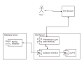 Deployment diagram


Remove ads
Adoption
In 2013, UML had been marketed by OMG for many contexts, but aimed primarily at software development with limited success.[12][27]
It has been treated, at times, as a design silver bullet, which leads to problems. UML misuse includes overuse (designing every part of the system with it, which is unnecessary) and assuming that novices can design with it.[28]
It is considered a large language, with many constructs. Some people (including Jacobson) feel that UML's size hinders learning and therefore uptake.[29]
Visual Studio dropped support for UML in 2016 due to lack of use.[30]
According to Google Trends, use of the term UML has declined since 2004 although leveled off in the last 5 years.[31]
History
Summarize
Perspective

UML has evolved since the second half of the 1990s and has its roots in the object-oriented programming methods developed in the late 1980s and early 1990s. The image shows a timeline of the history of UML and other object-oriented modeling methods and notation.
Origin
Rational Software hired James Rumbaugh from General Electric in 1994 and after that, the company became the source for two of the most popular object-oriented modeling approaches of the day:[32] Rumbaugh's object-modeling technique (OMT) and Grady Booch's method. They were soon assisted in their efforts by Ivar Jacobson, the creator of the object-oriented software engineering (OOSE) method, who joined them at Rational in 1995.[4]
UML 1.x
UML is originally based on the notations of the Booch method, the object-modeling technique (OMT), and object-oriented software engineering (OOSE), which were integrated into a single language.[14] UML was developed at Rational Software in 1994–1995, with further development led by them through 1996.[4]
Under the technical leadership of Rumbaugh, Jacobson, and Booch, a consortium called the UML Partners was organized in 1996 to complete the Unified Modeling Language (UML) specification and propose it to the Object Management Group (OMG) for standardization. The partnership also contained additional interested parties (for example HP, DEC, IBM, and Microsoft). The UML Partners' UML 1.0 draft was proposed to the OMG in January 1997 by the consortium. During the same month, the UML Partners formed a group, designed to define the exact meaning of language constructs, chaired by Cris Kobryn and administered by Ed Eykholt, to finalize the specification and integrate it with other standardization efforts. The result of this work, UML 1.1, was submitted to the OMG in August 1997 and adopted by the OMG in November 1997.[4][33]
After the first release, a task force was formed[4] to improve the language, which released several minor revisions, 1.3, 1.4, and 1.5.[34]
The standards it produced (as well as the original standard) have been noted as being ambiguous and inconsistent.[35]
UML 2
UML 2.0 major revision replaced version 1.5 in 2005, which was developed with an enlarged consortium to improve the language further to reflect new experiences on the usage of its features.[36]
Although UML 2.1 was never released as a formal specification, versions 2.1.1 and 2.1.2 appeared in 2007, followed by UML 2.2 in February 2009. UML 2.3 was formally released in May 2010.[37] UML 2.4.1 was formally released in August 2011.[37] UML 2.5 was released in October 2012 as an "In progress" version and was officially released in June 2015.[37] The formal version 2.5.1 was adopted in December 2017.[1]
There are four parts to the UML 2.x specification:
- The Superstructure that defines the notation and semantics for diagrams and their model elements
- The Infrastructure that defines the core metamodel on which the Superstructure is based
- The Object Constraint Language (OCL) for defining rules for model elements
- The UML Diagram Interchange that defines how UML 2 diagram layouts are exchanged
Until UML 2.4.1, the latest versions of these standards were:[38]
- UML Superstructure version 2.4.1
- UML Infrastructure version 2.4.1
- OCL version 2.3.1
- UML Diagram Interchange version 1.0.
Since version 2.5, the UML Specification has been simplified (without Superstructure and Infrastructure), and the latest versions of these standards are now:[39]
- UML Specification 2.5.1
- OCL version 2.4
It continues to be updated and improved by the revision task force, who resolve any issues with the language.[40]
Remove ads
See also
- Business Process Model and Notation – Graphical representation for specifying business processes
- C4 model – Technique for modelling software architecture
- Department of Defense Architecture Framework – Enterprise architecture framework
- DOT (graph description language) – File format
- List of Unified Modeling Language tools
- Real-Time UML – the application of the Unified Modelling Language (UML)
- MODAF – Enterprise architecture framework
- Model-based testing – Application of model-based design
- Model-driven engineering – Software development methodology
- Modeling and Analysis of Real Time and Embedded systems
- Object-oriented role analysis and modeling – Modeling method
- Process Specification Language – Set of logic terms used to describe processes
- Systems Modeling Language – General-purpose modeling language
Remove ads
References
Further reading
External links
Wikiwand - on
Seamless Wikipedia browsing. On steroids.
Remove ads