Top Qs
Timeline
Chat
Perspective
Technical illustration
Process of visually communicating technical concepts or subjects From Wikipedia, the free encyclopedia

Remove ads
Technical illustration is illustration meant to visually communicate information of a technical nature. Technical illustrations can be components of technical drawings or diagrams. Technical illustrations in general aim "to generate expressive images that effectively convey certain information via the visual channel to the human observer".[1]
Technical illustrations generally have to describe and explain the subjects to a nontechnical audience. Therefore, the visual image should be accurate in terms of dimensions and proportions, and should provide "an overall impression of what an object is or does, to enhance the viewer’s interest and understanding".[2]
Remove ads
Types
Summarize
Perspective
Types of communication
Today, technical illustration can be broken down into three categories[citation needed] based on the type of communication:
- Communication with the general public: informs the general public, for example illustrated instructions found in the manuals for automobiles and consumer electronics. This type of technical illustration contains simple terminology and symbols that can be understood by the lay person and is sometimes called creative technical illustration/graphics.
- Specialized engineering or scientific communication: used by engineers/scientists to communicate with their peers and in specifications. This use of technical illustration has its own complex terminology and specialized symbols; examples are the fields of atomic energy, aerospace and military/defense. These areas can be further broken down into disciplines of mechanical, electrical, architectural engineering and many more
- To help manufacture or replicate an invention[3]
- Communication between highly skilled experts: used by engineers to communicate with people who are highly skilled in a field, but who are not engineers. Examples of this type of technical illustration are illustrations found in user/operator documentation. These illustrations can be very complex and have jargon and symbols not understood by the general public, such as illustrations that are part of instructional materials for operating CNC machinery.
Types of drawings
Main types of drawings in technical communication are:[4]
- conventional line drawings,
- exploded-view drawings,
- cutaway drawings, and
- clip art images
Remove ads
Techniques

Technical illustration uses several basic mechanical drawing configurations called axonometric projection. These are:
- Parallel projections (oblique, planometric, isometric, dimetric, and trimetric), and
- many types of perspective projections (with one, two, or three vanishing points).
Technical illustration and computer-aided design can also use 3D and solid-body projections, such as rapid prototyping.
- In the natural sciences, "scientific illustration" refers to a style of drawing using stippling and simple line techniques to convey information with a minimum of artistic interpretation.
Remove ads
Examples
Technical Illustrations Gallery
 Small kitchen in perspective
 Conventional line illustration of an engine demonstrating perspective and line techniques
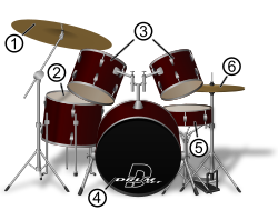 Illustration of a drum set
 Gallotia simonyi, example of pen and ink scientific illustration
 Broken view plan, showing the decks of a ship, drawn 1783


Further reading
- McDonnell, Phyllis Wood. With a chapter by Patrick (1994). Scientific Illustration: A Guide to Biological, Zoological, and Medical Rendering Techniques, Design, Printing, and Display (2nd ed.). New York, NY [u.a.]: Wiley. ISBN 978-0471285250.
- Bredekamp, Horst; Dunkel, Vera; Schneider, Birgit, eds. (2019). The Technical Image: A History of Styles in Scientific Imagery. Chicago, IL: University of Chicago Press. ISBN 9780226258980.
Remove ads
See also
References
External links
Wikiwand - on
Seamless Wikipedia browsing. On steroids.
Remove ads