Top Qs
Timeline
Chat
Perspective
Transposition tower
Type of electrical transmission tower From Wikipedia, the free encyclopedia

Remove ads
In electrical power transmission, a transposition tower is a transmission tower that changes the relative physical positions of the conductors of a transmission line in a Polyphase system. A transposition tower allows these sections to be connected together, while maintaining adequate clearance for the conductors. This is important since it distributes electrical impedances between phases of a circuit over time, reducing the problem of one conductor carrying more current than others.


This article needs to be updated. (March 2024) |
Double-circuit lines are usually set up with conductors of the same phase placed opposite each other. For example, a section of a line may be (top-to-bottom) phases A-B-C on the left, also phases C'-B'-A' on the right. The next section may be B-C-A on the left, also A'-C'-B' on the right. Therefore, the rotation on each side of the tower will be opposite.[1] Transposition helps to reduce the mutual coupling between conductors and between conductors and ground.[2] It also useful in mitigating issues like induced voltages in nearby telephone lines.[3]
Remove ads
Gallery
 Here, on the right the phases are rotated; on the left, two phases are swapped, thus the rotation sense changed.
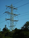 Transposition tower. On the right side, the phases are rotated upward, on the left side downward.
 Transposition in the span field of a 420 kV-line in Sweden


 Transposition on a single-phase line
 Transposition by using multiple towers
 Transposition by using elongated traverses


 154 kV double-circuit transposition tower.

Remove ads
See also
Wikimedia Commons has media related to Transposition towers.
External links
Wikiwand - on
Seamless Wikipedia browsing. On steroids.
Remove ads